UPnP Device Architecture
1.Motivation For UPnP
USB provides a universal solution to the PC plug and play problem. It has minimal configurations to be done by the user, user (genraly) doesn’t have to reboot or make configuration changes are to add a new device. At the same time, the USB architecture is is highly hierarchical .
Currently, numerous pervasive and cross platform technologies like (TCP/IP, HTTP, XML, UDP etc) are available. So , the question is, why not integrate them all to get a “Foundation of the Connected Home”
2.Introduction
UPnP targets at universal digital, open home networking platform that requires
- Zero configuration
- Reuse existing technologies so that we don’t re-invent the wheel and support from standard systems that already has most of these technology stacks in place.
UPnP was introduced by Microsoft Corporation at the Consumer Electronics Show in January of 1999. It is currently maintained by the UPnP forum.
3. Key Features
Major features provided by UPnP are
- Device connectivity
Devices can join and leave the UPnP network transparently, advertise their services, discover other devices and services, send events, and control other devices.
- Ad-Hoc networking
No dedicated network infrastructure have to be out in place for enabeling UPnP home network. Networks are configured on the fly without manual intervention. thus, it is a “Zero configuration network”
- Standard based Architecture
All foundation technologies used in UPnP are existing and proven. Thus, realizing UPnP in any platform is extremely simple. This also reduces the time-to-market.
- Platform and medium independence
UPnP can be implemented over any medium for which an IP stack is available. Thus, UPnP can be used to aggregate devices connected through phone lines, power lines, RF , Ethernet, WiFi (ya, it is RF again 🙂 ) etc
- Programmatic and manual device control
Devices in the UPnP network can be controlled programatically as well as manually
4.Building Blocks
Basic abstractions of the UPnP device architecture includes 3 major components . They are
- Devices
- Services
- Control points
Service is a unit of functionality implemented by a device. there can be 0 or more services present in a device.
Specifics about service implementations are defined by a separate UPnP forum working committee and are not part of the device architecture.
A service description will define “actions” ,input and output parameters , return value etc and will include mandatory device services. For example, an audio rendering device, such as a CD player, might have a service that provides the ability to play, stop, and pause audio content.
A “Control point” invokes the services provided by a device. They can control the device and request updates on state change of a service.
We will visit each of these topics in depth in later sections. However, first we need to get an understanding of the underlying technologies used in UPnP.
5.Groundwork
In this section, we will try and get a quick glance of the underlying technologies used in UPnP. This include
This section introduces
- URI
- IP Multicast
- HTTP
- HTTP over UDP
- XML
5.1 Uniform Resource Identifier
The world wide web stores information (web pages, images, data, video, songs etc) in the form of resources. A URI is a compact string used to identify a resource. URI folloes syntax specified in rfc2396. URI is further classified into URL and URN
A Uniform Resource Locator (URL) identifies a resource by location rather than by name or some other identifier. Thus the content in this location can keep change. A good to illustrate this is an arbitrary URL – http://example.com/quote-for-the-day . Each day, teh quote in this page changes. but, the URL remains the same and points to the same internet resource that generates the quote for the day.
A Uniform resource names (UR.N) is a unique and persistent identifier of a resource. It cannot be reused even after the resource cease to exist
Note: http://example.com domain is established by IANA to be used for illustrative examples in documents.
5.2 IP Multicast
A sender sends a multicast message to a multicst address (<IPAddress>:<port>) and all the members of this “host group” receives data from the sender. Any device interested in listening to multicasts join the group with an ICMP message and the router ensures that the device receives the message. Sender need not be a member of this group.
Multicast addresses are class D internet addresses. i.e range of addresses from 224.0.0.0 to 239.255.255.255 (with reservations)
UPnP control points and devices use the multicast address 239.255.255.250, and port 1900.Any source can send data to all UPnP devices and control points on a local network with this address. Thus UPnP network requires support of multicast capable IP routers.
Reach of multicast is controlled by using the Time To Live (TTL) field of IPv4 headers.TTL is decremented by 1 for each hop (router). A packet is transmitted only if TTL > 0.
Reach of multicast can also be restricted with administrative scope of IP multicast. 239.0.0.0 to 239.255.255.255 is administratively scoped IPv4 multicasts address space. (Termed IPv4 Local Scope). Network administrators partition this space and limit multicast range. Generally 239.255.255.250 falls within the IPv4 Local Scope and is the smallest of the administrative scopes.
5.3 HTTP
5.3.1 HTTP 1.0
Hyper Test Transfer Protocol 1.0 is a simple request-response protocol. The current HTTP 1.1 is built on top of this protocol. The major features of this protocol are discussed below.
In HTTP 1.0, connection is closed by server after each request. This makes it a stateless protocol. States are stored in “cookies” and are presented to the server with each request.
Request structure:
The initial line of the request specifies the “METHOD”. This is followed by more “header” lines specifying variables and values and an optional message body (file, query data etc).
Initial request line:
<method name> <request path> <http version>
Eg: GET /path/to/file/index.html HTTP/1.0
Response code will indicate outcome of action
Eg:
HTTP/1.0 200 OK
HTTP/1.0 404 Not Found
Header lines:
Provides information about request, response or object sent in message body.Format is
header-name: Value
Message body:
In response, this is used to return requested resource to client or explanation text of an error
An HTTP 1.0 transaction to retrieve file at URL http://www.example.com/path1/file1.html has the following steps
- First open a socket at http://www.example.com at port 80 (default http port)
- Send following through the socket
GET /path1/file1.html HTTP/1.0
From : someuser@example.com
User-Agent : HTTPTool/1.0
(blank line)
- Server responds with something like
HTTP/1.0 200 OK
Date: Fri, 20 Nov 2002 23:59:59 GMT
Content-Type: text/html
Content-Length: 1354
<html>
<body>
<h1>Sample Header Text</h1>
(more file contents)
.
.
.
</body>
</html>
5.3.2 HTTP 1.1
The major improvements brought in by HTTP 1.1 are discussed here.
HTTP 1.1 supports multiple transactions over persistent connection by default. Requests are sent in a pipelined queue.This is applicable to the responses also. Once the transactions are done, the client uses “connection: close” header to denote end of connection. It can also be used by server to denote that connection is being terminated.
HTTP/1.1 100 Continue is used in slow connections to indicate data is on the way 🙂
HTTP 1.1 has support for data caching. All responses contain a GMT time stamp with the “Date:” header. “If-Modified-Since” or “If-Unmodified-Since” headers can be used to request newer version of the resource.
HTTP 1.1 Chunked encoding allows response to be sent even before total length is known. This mechanism uses uses the “Transfer-Encoding” header set to “chunked”
Sample of chunked encoding transfer
HTTP/1.1 200 OK
Date: Fri, Dec 2002 23:59:59 GMT
Content-Type: text/plain
Transfer-Encoding: chunked
1a: ignore-stuff-here |size of chunk in hex
abcdefghijklmnopqrstuvwxyz |chunk data
10 |size of chunk in hex
1234567890abcdef |chunk data
0 |0 to denote end of chunks
some-footer: some value
another-footer: another value
(blank line)
The footers should be considered as if they were sent before the data
HTTP 1.1 allows multiple domains to be served from same ip address. this is called multihoming and is facilitated by the “HOST” header.
eg:
GET /path/file.html HTTP/1.1
Host: http://www.host1.com
(blank line)
HTTP 1.1 also accepts absolute URLs
GET http://www.intoast.com/path/file.html HTTP/1.2
Summary of HTTP 1.1 server requirements are:
- Host header with each request
- Accept response with chunked data
- Support persistent connections or use Connection: close with each request
- Handle 10 continue response (by ignoring it)
Summary of HTTP 1.1 client requirements are:
- Accept absolute URL
- Accept request with chunked data
- Include Date: header in each response
5.3.3 HTTP Extension framework
HTTP provides a mechanism to address private headers and requests by extending a single HTTP message. this feature allows to defines few HTTP header fields to denote extensions.
5.4 HTTP over UDP
UPnP Exploits the connection less model of UDP and uses it primarily for sending HTTP multicast messages.
- HTTPMU for multicasts
- HTTPU for UDP unicasts
UPnP introduces 3 new headers to resolve issues arising from HTTP over UDP.
- MX request header
To avoid chances of large number of responses coming back to the sender (Host) at the same time, HTTP over UDP uses a new header which denotes the number of seconds the multicast UDP HTTP resource can wait before it can send a response initiated by a multicast request.
The resource generates a random number between 0 and MX and waits for that much time to send response. Thus, if multiple responses are there, they will be spread out between 0 and MX.
- Sequence (S) general header
The Sequence header is used to associate a unique URI with a request-response pair. It is Generated at request time and uses the same URI used in response
- Alternate (AL) general header
This header is used for multiple “Location:” header transmission
Request-URI in case of MulticastHTTP means the recipient and not the requested resource. Thus the “*” request URI means, send to all.
Eg: M-SEARCH “*” HTTP/1.1
5.5 Extensible Markup Language (XML)
XML is a documentation language used to specify structure of data and how various elements relate. An XML document contains markup and character data. Markup gives the document its structure while character data is the actual content of the document. An XML document type definition (DTD) or XML schema (template) taht specifies teh constraints of data in teh document.
A typical XML document will have a prologue, root and misc part.
The Prologue contains XML declaration, processing instruction, comments, whitespace and a document type declaration.
Sample deceleration:
<?xml version=”1.0″ encoding=”UTF-8″ standalone=”no”?>
Standalone means no external dependencies
An XML DOM or document object model can be considered as a A programmatic view of the xml document as trees and nodes. DOM APIs are used to access and manipulate XML docs.

Sample representation of XML DOM
6. UPnP Protocol Stack

UPnP protocol stack
The figure shows an IP based protocol stack . (even though UPnP can be implemented over any medium/base protocol supporting socket based communication). Further discussion assumes an IP based protocol stack.
7. UPnP device operation
Basic abstractions of the UPnP device architecture includes three major components.
- Devices,
- Services
- Control points
A physical device may have more than one root device. A root device can have multiple embedded devices. Thus UPnP provides a very flexible logical arrangement.
A device will have a state table that maintains state variables. All operations on devices are based on the states of these state variables.
There are 6 phases of operation for any UPnP device. they are
- Addressing
- Discovery
- Description
- Control
- Eventing
- Presentation
first we will have a breif description each phase. We will visit each in detail later
7.1 Addressing
A UPnP device aquires an address using either DHCP or AutoIP as soon as it joins the network. This enables Adhoc , Zero Configuration networking.
7.2 Discovery
As soon as a UPnP device gets an address, it searches for presence of other UPnP services in the network. It also announces presence to other devices present in the network. This is done using Simple Service Discovery Protocol (SSDP) over HTTPMU
7.3 Description
Once a device identifies other devices available in the network, it obtains service details of required devices in the network. The device should also provide its capability details to other devices requesting it.
7.4 Control
A Control point can invoke the functionality provided by a service via SOAP messages. Simple Object Access Protocol (SOAP) is a Microsoft technology used for cross platform RPCs. Once a device service receives a message, it has to act upon it
7.5 Eventing
UPnP follows a publisher-subscriber model to notify monitoring/interested control points about change in the state variable. General Event Notification Architecture (GENA) is used for event notifications.
7.6 Presentation
UPnP devices also provide a browser based, manual interface. It is HTML based and the presentation URL is part of device descriptor document (DDD) that is provided as part of the description process.
Now, let us visit each of the stages in detail.
8. Addressing
DHCP allows two modes of Addressing
- DHCP – which requires dedicated infrastructure (a DHCP server)
- Auto IP – a true AdHoc mechanism with lots of limitations on network reach
8.1. Dynamic Host Control Protocol (DHCP)
For DHCP, a server sits and allocates IP addresses to all newly arriving devices. It relies on UDP based transport and the server receive requests on port 67. The response is posted to the hosts on port 68.
DHCP alows three allocation modes
- Automatic – where the IP address is allocated from a pool of addresses upon request by a client
- Manual – where the admin configures the IP of each host and the DHCP server conveys it to hosts on request
- Dynamic – where the DHCP server “Leases” an IP to the host for a limited period of time after which the device has to renew the IP.

Basic DHCP flow
8.2 AutoIP
First and foremost, AutoIP is Not a DHCP replacement. Rather, it is a temporary solution when the DHCP server is down. AutoIP address assignment happens in two major steps.
Step1:
The device selects a candidate IP address within the non-routable address range (169.254/16) with default class B subnet mask 255.255.0.0. The first and last 256 addresses in this range are reserved and MUST NOT be used.
•The Non-routable address range (169.254/16) do not cross network gateways and are known as LINKLOCAL net range of IPs
The selection algorithm is implementation dependent and is not defined by AutoIP. However, it is recommended to use device’s or control point’s Ethernet hardware MAC address as seed for randomization.
Step 2:
Send out an Address Resolution Protocol (ARP) probe for the chosen address. If no one responds, then it is yours 🙂
ARP is generally used to determine the MAC address of an IP address holder. Here it is used in an unusual way. Recommended probing pattern is four times at two-second intervals.

AutoIP sequence
AutoIP addressed devices will not be visible beyond the local network segment. IP packets whose source or destination addresses are in the 169.254/16 range will not be sent to any router for forwarding. In case this has to be by-passed, senders must ARP for the destination address and then send the packets directly to the destination on the same link. Devices and control points MAY assume that all 169.254/16 destination addresses are on-link and directly reachable.
8.3 UPnP device Addressing
Steps in UPnP Device Addressing are as follows:
- If DHCP is available, get it from there.
- else, use Auto-IP to get the IP
- if DHCP becomes available afterwards, get IP from there
Suggested recheck period for DHCP server availability is 5 minutes. However, the current IP address should be relinquished only after the current connections are over.
Once addressed, do a DNS registration if required. DNS addresses can be preconfigured or obtained from DHCP server.
9. Discovery
Once addressed, a device is ready to provide services to other devices in the network and control point, can start utilizing the available services. Discovery allows control points to search for devices and services matching a search criteria.
Devices advertise and inform. Control points discover and select. All this is done using simple service discovery protocol (ssdp)
9.1. Simple service discovery protocol (SSDP)
SSDP is a protocol for small networks that runs over HTTPMU. It facilitates a mesh model where there is no central store of information . However, it gets ugly as number increase.
UPnP adds two concepts to generic SSDP. They are
- Service type
- Unique Service Name (USN)
USN is a URI to identify functionality of a resource. It is a 128 bit Universally Unique Identifier (UUID). Its generated based on the host network address, a timestamp and a randomly generated component. (In linux based systems the uuidgen utility can be used to generate a uuid.)
Eg:
service type: “printer”
USN: “uuid: 2fac1234-31f8-11b4-a222-08002b34c003”
There are two types of SSDP requests.
- Discovery request:
Sent by a device to know the devices that have come in before itself on a per service basis.
- Presence announcement:
Sent only at the time of joining the network and leaving the network
As a result of this model, neither server or client will have to send out steady stream of messages
9.1.1. SSDP Discovery request

SSDP Device Discovery header template
The headers in ssdp are
- M-SEARCH: Search request broadcast method
- ST: Header to specify search target
- MX: Response delay limit to avoid cluttering as described in HTTP over UDP
- MAN: Always set to ssdp:discover
SSDP supports very simple searches without logical expressions, name-value pairs etc. Legal search type (ST) values are:
- ssdp:all : to search all UPnP devices
- upnp:rootdevice: only root devices . Embedded devices will not respond
- uuid:device-uuid: search a device by vendor supplied unique id
- urn:schemas-upnp-org:device:deviceType- version: locates all devices of a given type (as defined by working committee)
- urn:schemas-upnp-org:service:serviceType- version: locate service of a given type
All SSDP requests are sent to 239.255.255.250 on teh default port 1900. However this can be overridden with SEARCHPORT.UPNP.ORG header.
SSDP start line will always be one of the following
- NOTIFY * HTTP/1.1: In case of advertisement
- M-SEARCH * HTTP/1.1: In case of search
- HTTP/1.1 200 OK: In case of response
SSDP also supports additional proprietary headers. Some of the defined headers include:
- BOOTID.UPNP.ORG
- CONFIGID.UPNP.ORG
- NEXTBOOTID.UPNP.ORG
- SEARCHPORT.UPNP.ORG
Domain (vendor) specific header format will be of the form
- myheader.example.com: “some value”
9.1.2. SSDP Discovery response
SSDP response is a unicast reply to the sender of search broadcast. It starts with HTTP success response followed by few headers. The response is sent to the same port that made the request.

SSDP response
SSDP response includes:
- Cache-control: This header is part of HTTP cache control settings. UPnP uses max-age for this field.
- Date (recommended): Response generation timestamp
- Ext: Confirms that man header in request (ssdp:discover) was understood
- Location: URL to the device description document of the root device
- Server: concatenation of OS name, OS version, Product name and product version
- ST: Same as that specified in the discovery request
- USN: Unique service name. It takes different value formats depending on ST. Some examples are
- uuid:device-UUID:upnp-rootdevice
- uuid: device-UUID
- uuid:device-UUID:urn:schemas-upnp-org: device:deviceType:ver
- uuid:device-UUID :urn:schemas-upnp-org:device:serviceType:ver
- urn:domain-name:device:deviceType:ver
- urn:domain-name:service:serviceType:ver
USN+ST provide unique identification to the service.
9.1.3. Presence Announcement (Advertisement)
When a UPNP device is joining, leaving, having location change or expiration info change, it has to send an advertisement to let other devices be aware of the changes that are happening.
The presence announcement is sent To standard multicast address (239.255.255.250:1900) where all control points listen.
Presence announcement uses (General Event Notification Architecture)GENA which relies on the NOTIFY method over HTTPU/HTTPMU.
There are three kinds of advertisement.
- Device available : ssdp:alive
- Device unavailable : ssdp:byebye
- Update : ssdp:update
Advertisement sends info about root, embedded devices, and how to find them. So, if a root device has
d embedded devices, s embedded services and k distinct service types, There will be 3+2d+k advertisement messages.
UPnP 1.1 adds 4 new header fields to SSDP
- BOOTID.UPNP.ORG
A non-negative 31-bit integer, ASCII encoded, decimal, without leading 0s which is increased each time a device (re)joins the network and sends an initial announce. It can also be the same as the field value of the NEXTBOOTID.UPNP.ORG header field in the last sent SSDP update message.Otherwise same value is used in all repeat announcements, search responses, update messages and eventually bye-bye messages. A convenient mechanism is to set this field value to the epoch time of initial announcement
- NEXTBOOTID.UPNP.ORG
Indicates the field value of the BOOTID.UPNP.ORG header field that a multi-homed device intends to use in future announcements after adding a new UPnPenabled interface
- CONFIGID.UPNP.ORG
A non-negative 31-bit integer, ASCII encoded, decimal, without leading 0s that represents the configuration number of a root device. The configuration of a root device consists of the following information:
- the Device Descriptor Document of the root device and all its embedded devices,SCPDs of all the contained services
- control points can parse this header field to detect whether they need to send new description query messages.
the values ranges from 0 to 16777215 (2^24-1) and higher numbers are reserved for future use
- SEARCHPORT.UPNP.ORG (optional)
9.1.3.2. ssdp:alive advertisement

SSDP Alive Advertisement
This notification is sent when joining a network with one of the following notification type :
- upnp:rootdevice
- uuid:device-UUID
- urn:schemas-upnp-org:device: deviceType:ver
- urn:schemas-upnp-org:service: serviceType:ver
- urn:domain-name:device:deviceType:ver
- urn:domain-name:service:serviceType:ver
USN can be one of
- uuid:device-UUID::upnp:Rootdevice
- uuid:device-UUID
- uuid:device-UUID::urn:schemas-upnp-org:device: deviceType:ver
- uuid:device-UUID::urn:schemas-upnp-org:service: serviceType:ver
- uuid:device-UUID::urn:domain-name:device:deviceType:ver
- uuid:device-UUID::urn:domain-name:service:serviceType:ver
9.1.3.2. ssdp:byebye advertisement
This notification when the device is leaving the network

SSDP byebye
9.1.3.3. ssdp:update
This notification is sent when a UPnP enabled interface is added or removed from the multi-homed device. This is applicable to all root and embedded devices. The BOOTID.UPNP.ORG header is increased when ssdp:update is sent.

SSDP Update
10. Description
Control points gets the device and service descriptor URIs from discovery phase. Now, the next step is to read and understand the required descriptor documents.
Descriptor documents are written in XML following the Schema provided by UPnP forum.
Descriptors come in two logical parts
- Device Descriptor
- Service Descriptor
These XMLs are retrieved using HTTP GET method.
10.1 Device Descriptor Document
Devicve descriptor document describes physical and logical containers. It contains the device identifiers and list of services provided by the device.

Device Description Document
The DDD spsecfies a UDN which is the unique device name and a UPC (universal product code). UPC is a 12 digit all-numeric code ID for consumer package.
The DDD also contains list of services and the service description document(SCPD) URL. Specific requests to the service can be sent to the “control URL” and event subscriptions are sent to the “EventSub URL”.
10.2. Service Descriptor Document (SCPD)
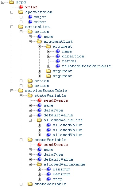
SCPD document
The SCPD primarily contains the list of all actions the service provides. It also contains an argument list.
One or more arguments may be marked as return value and each argument corresponds to a state variable.
The service state table describes the state variables. The sendEvents attribute denotes eventing status of the state variable. If it is set to “yes”, an event will be sent when the state variable changes. The allowedValueList and allowedValueRange determine the legal values of the state variables.
10.3. Retrieving Descriptors

Retrieving descriptors
First get device descriptor, parse it to get service descriptor URL, then get requires service descriptors.
11. Control
When services are distributed over a system, one component cannot directly access data in another component or invoke services directly. So, we have to use a client-server message passing like mechanism where each component is a mini-server. Thus devices in the network can make simple calls to a network based remote entity as if it is a local component.However, this requires components to meet the following minimum requirements
- A message based protocol with request, response, error invoking etc.
- A Platform independent data representation to package argument parameters
- Either predefined types or mechanism to pass type info
- An Optional security feature
In case of UPnP, service requests are made to the controlURL sub element of the service element in the device descriptor. As long as the discovery advertisement has not expired, service can be assumed to be available.
UPnP uses Simple Object Access Protocol (SOAP) for controlling other device services.
11.1. Simple Object Access Protocol (SOAP)
SOAP is an XML based mechanism for web based (over HTTP) messaging and remote procedure call mechanism. It consists of 4 main parts.
- SOAP envelope
An XML schema based infrastructure defining processing rules of the message. It is the outermost container of SOAP messages
- SOAP encoding rule
An XML schema for defining user defined data types
- SOAP bindings
Conventions for using different transport protocols that Generally uses HTTP
- SOAP RPC representation
For representing RPC calls and responses
Any system capable of packing and unpacking XML can use SOAP since tt is platform independence and it can pass complex messages and data.
SOAP message envelope <envelope> has two child elements –
- <Header> [optional]
It contains auxiliary information for authentication, transactions and payments. It can contain unlimited number of child elements.
- <Body> [required]
Contains core of messages
11.1.1. SOAP over HTTP
A UPnP SOAP message is sent as an HTTP POST to the control URI of the service obtained from descriptor document. The Content type will be set to “text/xml”.
SOAP introduces a a new header “SOAPAction” into HTTP. It contains a URI that indicates intention of the soap request. This URI need not point an actual web resource since it is used by the recieving web server to route the request. An empty string (“”) implies, the intent can be known from the HTTP request URI. No value means no indication about the intent.

Sample of a SOAP Message over HTTP
SOAP Uses HTTP Extension framework and introduces the MAN header and modifies POST to M-POST. M-POST requires HTTP server to read and understand the URI in MAN. First request is sent without MAN. If it fails with 405(method not allowed), then retries with M-POST. If the retry fails, then the whole request fails.
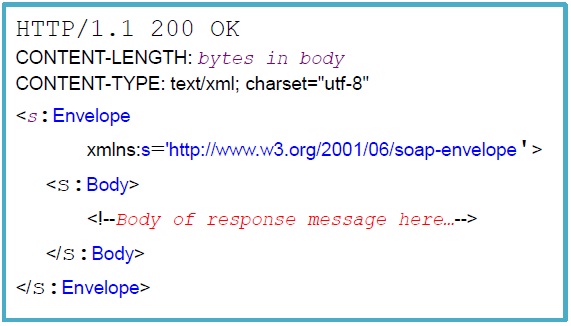
Soap Response
SOAP HTTP response is also a XML document where the <Body> contains the encoded result instead of the method call. Void methods omit <return> in the body
11.2. UPnP Action Request and Response over SOAP
Action request is sent to the service control URI with the action name, argument name and argument values as described in the service descriptor document.

UPnP action request over SOAP

SCPD XML showing action and argument list
Upon receiving the request, the service has to respond within 30 seconds.
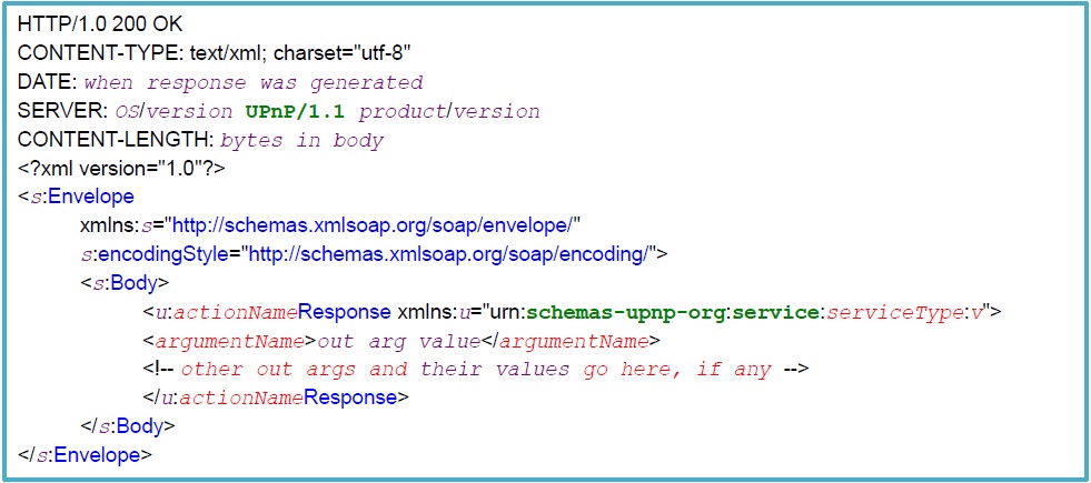
SOAP Response with HTTP Header
If large amounts of data has to be transferred, it is recommended to do an out of band transfer, i.e. publish URL as part of SOAP and later get it using HTTP GET. Error response follows a similar schema with error values.
12. Eventing
UPnP eventing uses General Event Notification Architecture (GENA) over HTTP. It follows a subscriber-publisher model where the services are publishers and control points are subscribers.
Eventing begins with a subscription request from the control point to the event subscription URL of the service. The publisher (service) responds with a subscription ID and duration of subscription.
GENA brings in 3 new HTTP methods:
- SUBSCRIBE
- UNSUBSCRIBE
- NOTIFY
It also introduces the following HTTP headers:
- CALLBACK : Used by subscriber to register notification URL
- NT : Notification type
- NTS : Notification sub type
- SID : Subscription ID generated by publisher, used by both parties
If a service state variable is marked as evented in the SCPD , control point can subscribe to notifications in case there is a change int eh state variable value.

Evented state variable
GENA uses XML based event messages whic includes state variable name and UPnP template language for eventing. An initial event message is sent upon subscription which includes all subscribed state variable names and states. The publisher maintains an event notification counter known as “Event key” that is incremented and embedded into each event notification.
UPnP eventing Schema
12.1 Event Subscription
A common event subscription is made to all evented state variables in the service. The event subscription request will also contain the CALLBACK header which specifies the URL to which event notifications are to be sent.

Event Subscription request
the event subscription response will include the HTTP response code and the subscription UUID (SID) (if success).

Subscription Response
The subscriber can send a renewal or cancellation request that wil be identified by the published by the SID.

subscription renewal request

Subscription Cancellation
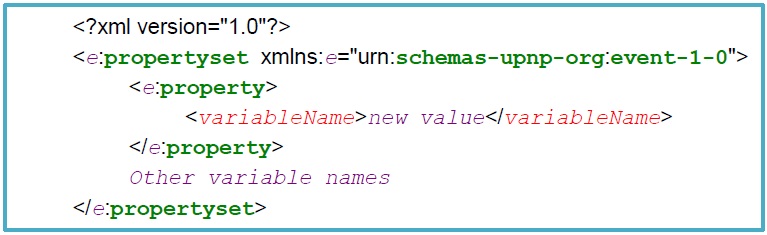
12.2 Event Message
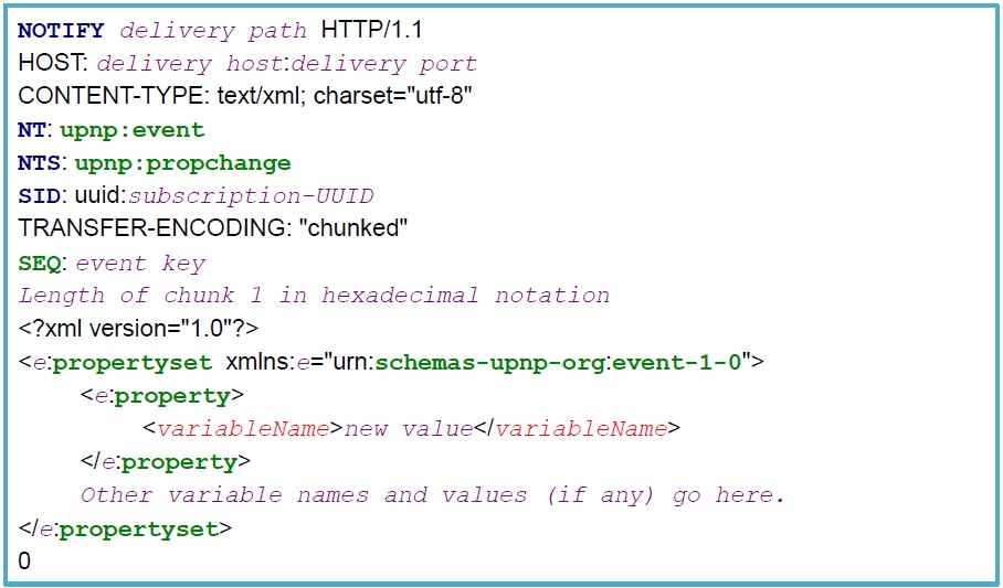
Unicast event message
Generally event notifications are sent to the registered callback URL as a unicast. The receiver acknowledges the notification with the appropriate HTTP response. However, there is also an alternate mechanism to publish events as a multicast to 239.255.255.246:7900.

Multicast event message
13. Presentation
UPnP also has provision for a browser based control of the device . The Presentation URL is part of Device Descriptor Document.
14. Summing up

Intel SDK – libupnp
Every UPnP device/control point have a specialized HTTP server Assisted by an XML Parser. They process and route the messages. Messages are routed into the corresponding Protocol stack for processing
Broadcasts are done over UDP at standard ports

rajnesh malik said
Very nice article…
vysakhpillai said
Thanks 🙂
Anand Kumar said
Awesome article about UPnP
rajesh gupta said
Very detailed information…
hl2mukkel said
This is the best and most in depth article I’ve seen yet!9
Moe said
I have been searching around the NET to find a good and consist doc about UPnP and HTTP, this one was best so far big thumb.
Hero Hunters hack said
What’s up everybody, here every one is sharing these kinds of familiarity, so it’s nice
to read this website, and I used to visit this web
site daily.